Reverse Engineering a 90’s Research Robot
I bought this 25+ year old robot at auction in a non-functioning state knowing almost nothing about it. The robot is a Nomadic Technologies N150. It has an interesting omnidirectional drive train and an array of sensors intended to be used for SLAM.
I disassembled the entire robot to reverse engineer it. After figuring out how the drive control worked, I made a few wiring modifications, installed new batteries, and added a microcontroller to interface with the original motor drivers.
After getting the robot functioning, I wired in an old playstation controller to manually control the drive motors.

Project Video
Since virtually no information about these robots is available on the internet, I chose to document the entire disassembly and testing process in depth so that it may be a helpful resource to anyone else trying to restore one of these. Skip to 44:20 to see the robot going for a test drive at the skatepark!

The unique drivetrain of this robot uses 3 wheels which are all driven by one motor. A second motor steers the wheels by rotating all 3, keeping them parallel with each other. The body of the robot maintains the same orientation regardless of which direction it is driving in.


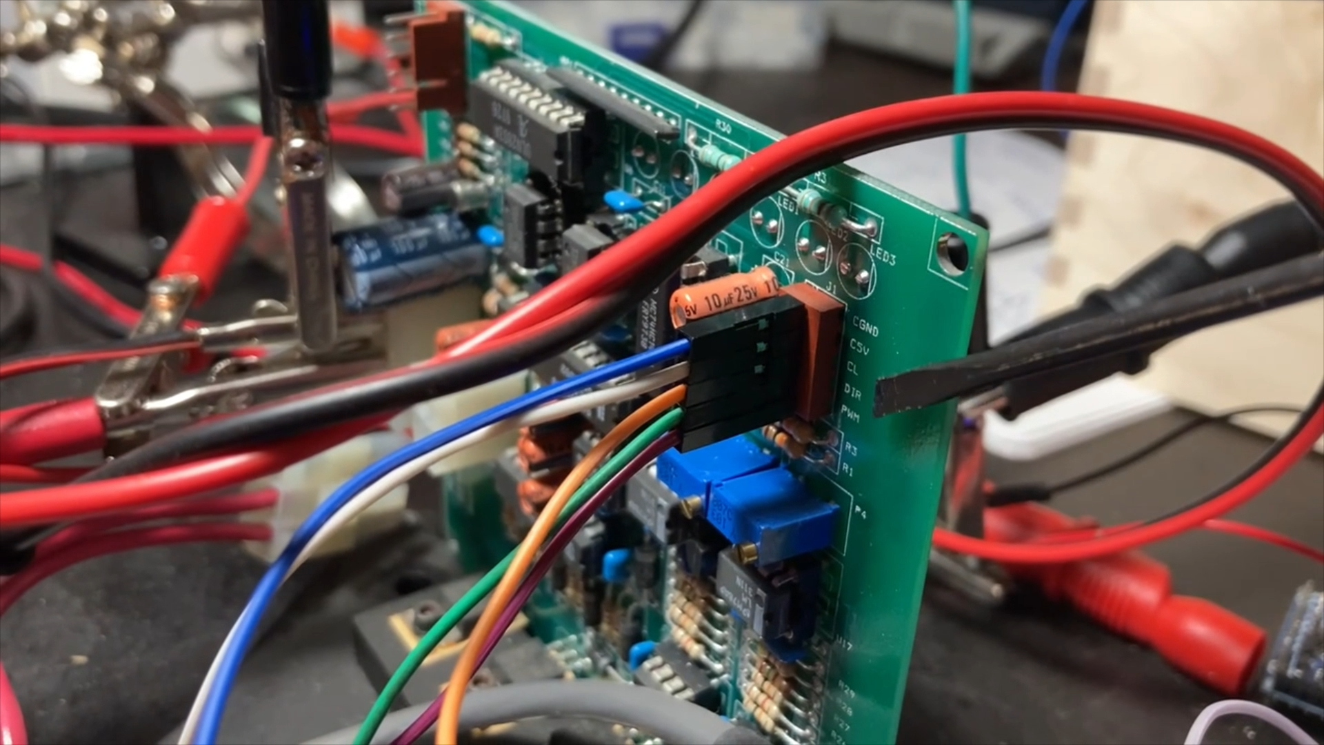
These are the main electronics I reverse engineered in order to interface a modern microcontroller with the existing drive controls. The central triangular PCB stack performs power distribution and switching, as well as breaks out the signal pins for the motor drivers. I figured out the dual 12v/24v power system so that I could install new batteries. I determined the pinouts of all the connections I needed to break into for motor control. The 3 smaller vertical PCBs around the perimeter are brushed motor drivers. I figured out how the enable, PWM, and direction pins were routed and connectorized. I also figured out how to wire in a switch and emergency stop.
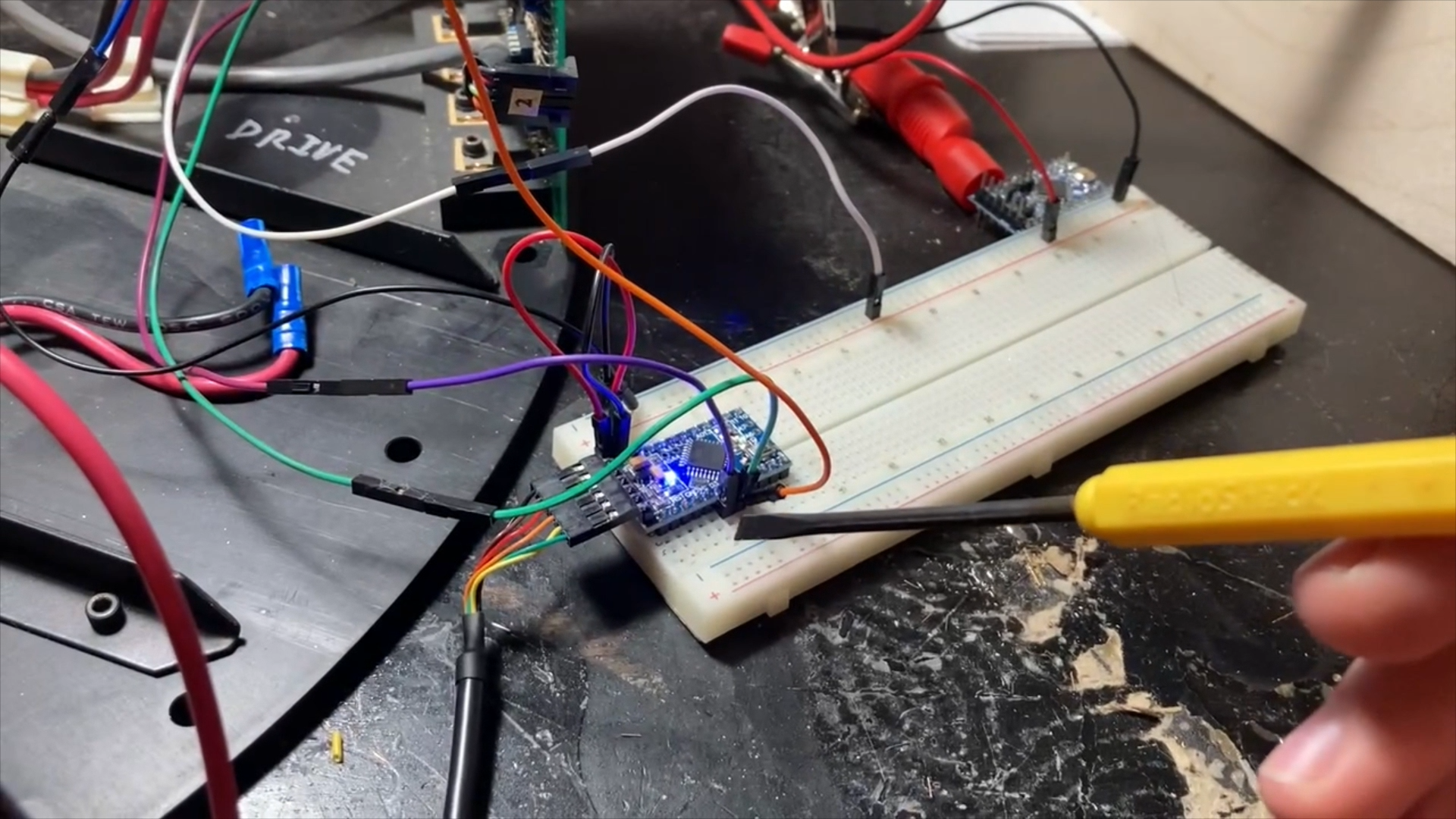
Here I'm doing some bench testing with a breadboard to inject PWM, Direction, and Enable signals into the motor driver. This verified my plan for taking control of all 3 motors.

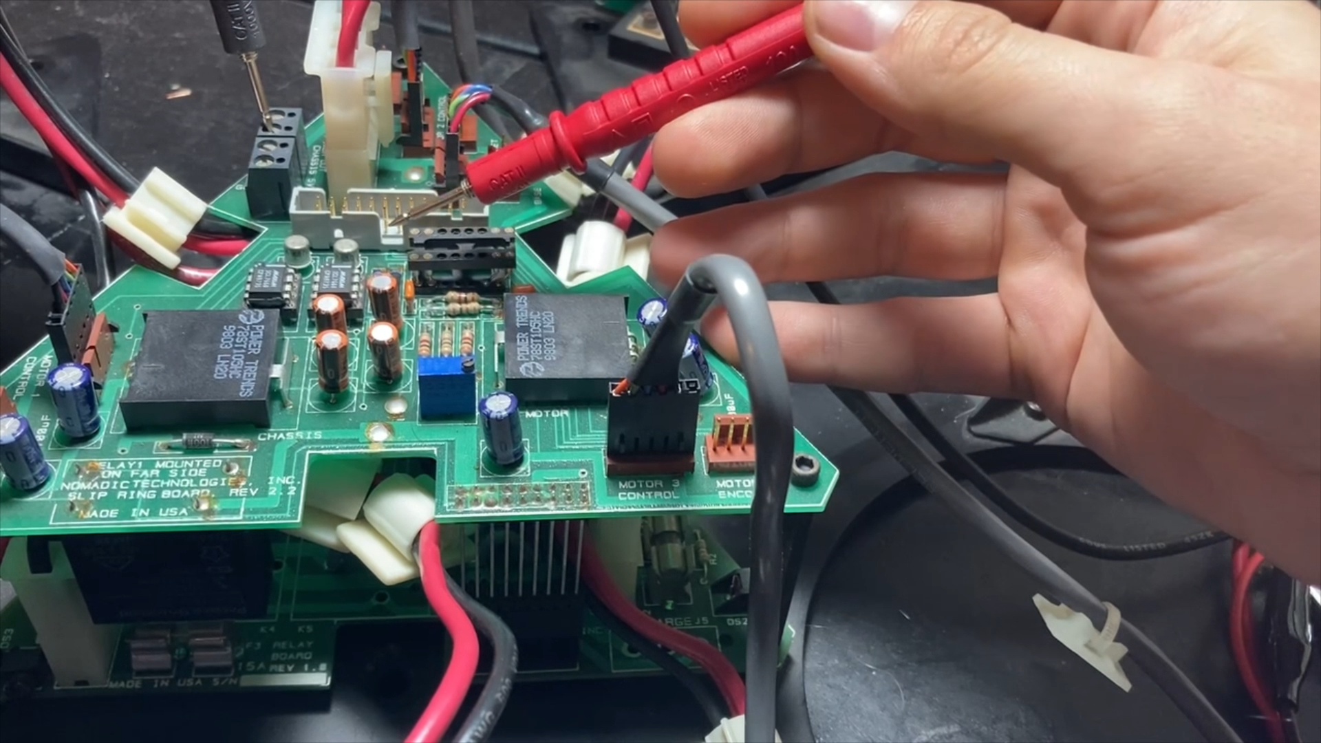
I beeped out the main 24 pin header which connects the lower PCB to the top of the robot through a large slip ring. I found all the pins I needed to interface with immediately and noted down the connections for the others so that I can read the encoders and limit switches in the future.


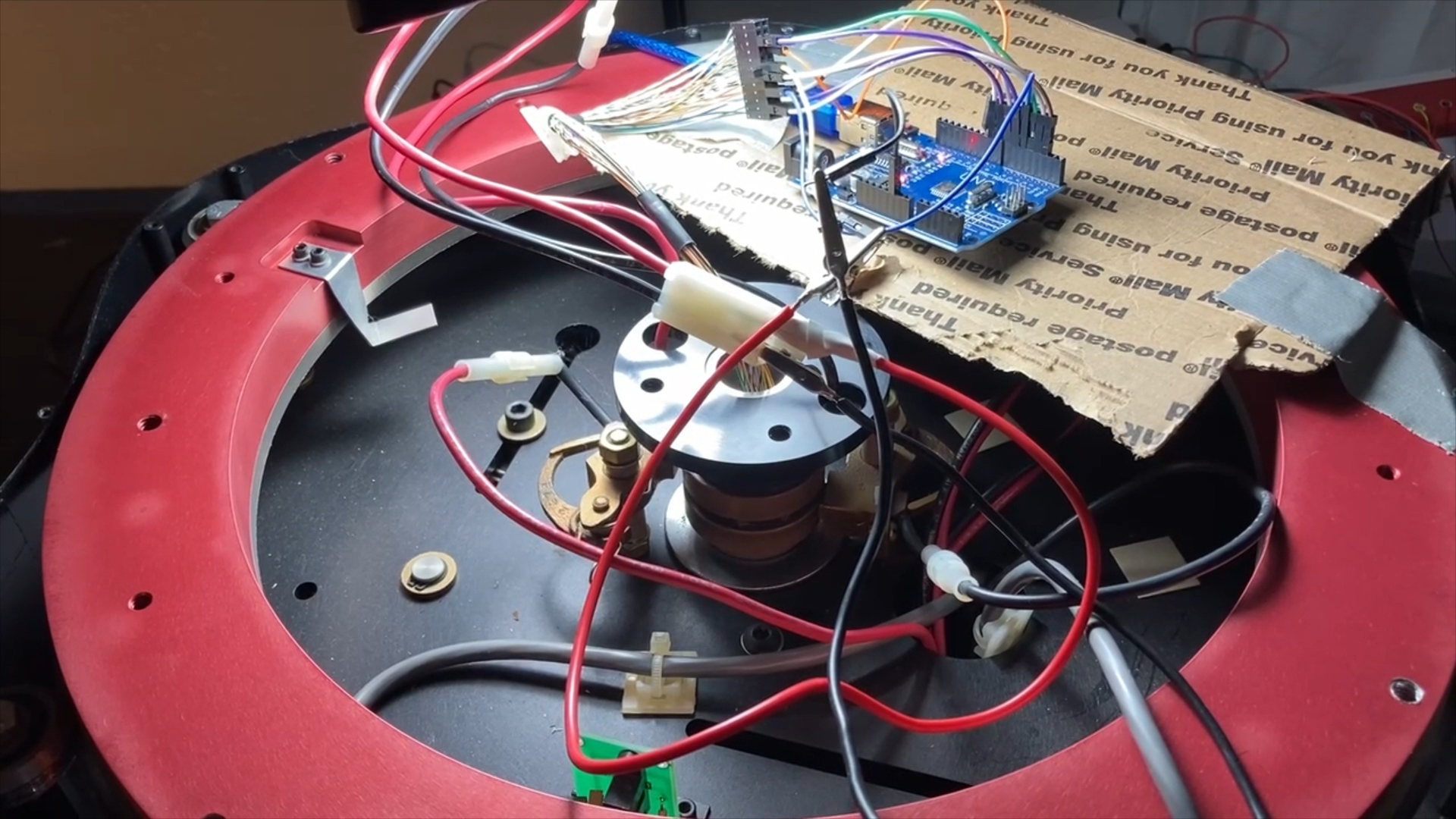
I temporarily wired in 3 random DC motors I had laying around so that I could bench test simultaneous independant control of all 3 drivers.

I used a wired PS2 controller to manually control the robot. I used this controller because it can be read via SPI easily with an arduino. I modified its cable so that it could plug right in to an existing header on the top of the robot.

I reassembled the necessary components to test all my modifications on the actual hardware it would be running.

I soldered together this protoboard to securely handle all the electronics once I was done verifying the circuit on a breadboard. The microcontroller is a Teensy 4.0. It contains a DC/DC converter to power the Teensy, a large 24 pin connector for the signals that go through the slip ring to the base of the robot, a smaller 16 pin header for the cable which reads the PS2 controller, a connector for the emergency stop switch which opens the circuit energizing the relays that provide power to the motors, and a final connector for the on/off switch, which cuts power to the microcontroller.

I 3D printed a mount with heat set inserts to hold the protoboard in the top of the robot using existing threaded holes.
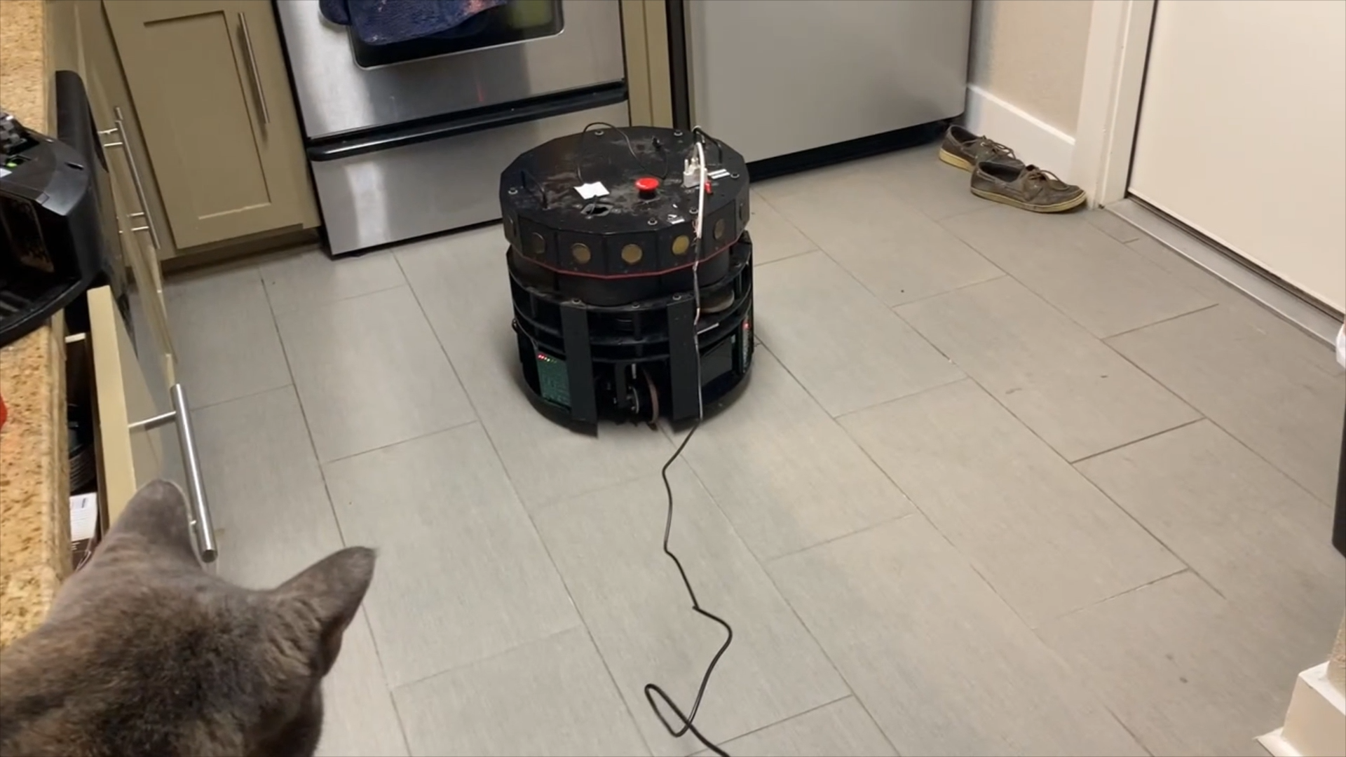
I loosely reassembled the necessary parts and went for an initial test drive around the house.

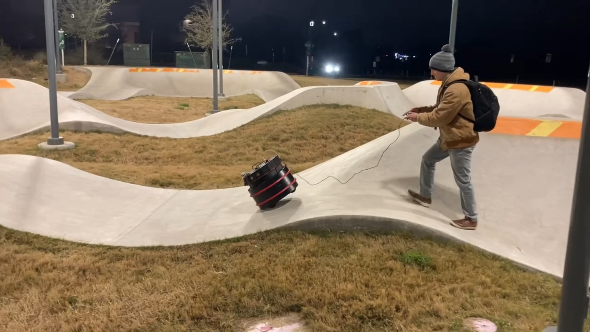
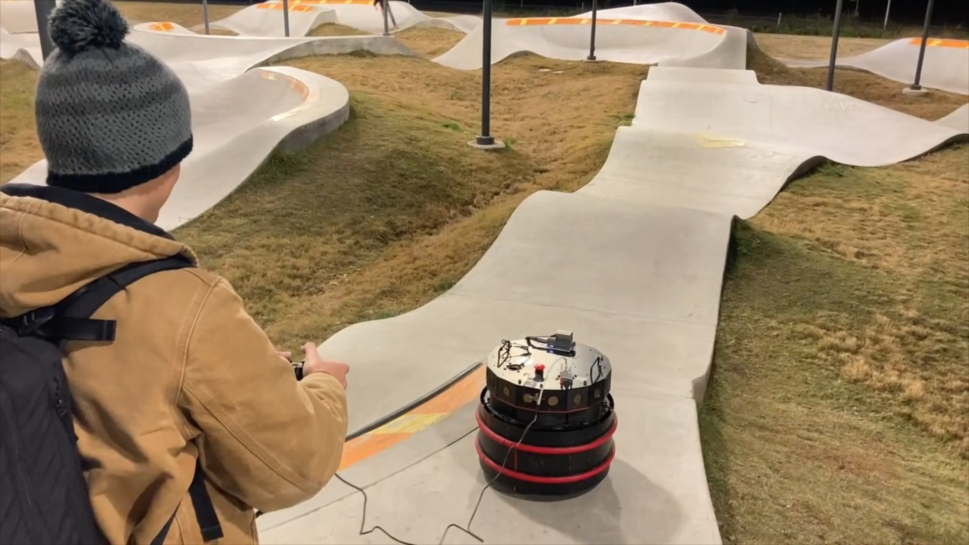
After completing final assembly, I took the robot for a ride at the local skate park. This winding sloped track is certainly not the intended use case for the drive train, but it performed impressively well.


This was a fun project and I certainly got some funny looks at the skatepark. It performed better than expected until eventually flipping over on a curved slope. It was barely damaged, suffering a failure in the connection to the playstation controller. In the future, I’ll get the robot driving autonomously so that I can experiment with SLAM via the 16 onboard sonar modules and array of bumper sensors.