Project Mecha Bevo
This was a group project for a UT graduate course, Robot Mechanism Design, in which we created a steerable walking robot driven by a unique dynamically adjustable linkage mechanism. I was in charge of all the electronics and programming, also contributing to the mechanical design and overall assembly.
Group Members: Connor Hennig, Umesh Malepati, Clay McPherson, Tyler Watts
See our page on the course wiki here: Wiki Link

Project Video
This video is a summary of the project. It demonstrates the robot walking and explains how it works.

This sketch shows the basic linkage mechanism used to drive the feet. A motor drives the input link (upper left) at a constant speed ω. The relative location of point C is moved up and down by the steering servo to adjust the length of the stride. all 6 feet perform stride cycles at exactly the same rate because they are all driven by the same motor by a series of timing belts. Steering is achieved via the servo adjusting the linkage to create a longer stride on one side and a shorter stride on the other. See a more in depth analysis of the stride length by Connor Hennig linked here.

This large scale prototype served as a proof of concept for the walking gait linkage mechanism. A marker was fixed to the “foot” allowing the stride path to be visualized. The position of the variable joint could be adjusted along the x or y axis in the central indexed slot by loosening a single bolt. This proved that earlier simulations were feasible in a real world model, and that the stride length could be effectively adjusted by altering the position of one grounded revolute joint.

This diagram shows how I wired the electronics. The microcontroller was an arduino uno. The DC motor and servo were used parts of unknown make and model. Multiple linear voltage regulators were used in parallel to tolerate the current throughput of the servo. This is an inefficient means of DC/DC conversion compared to a switching buck converter, but these parts were readily available on hand at no cost and battery longevity was not a concern. An L298N with breakout board was used to drive the DC motor in both directions at variable speed. The radio receiver was a cheap no-name part from china.
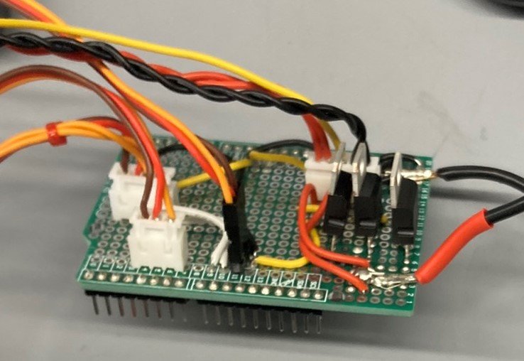

I connectorized the harnesses for important subsystems so that parts could be disconnected and swapped for troubleshooting, testing, and easy assembly. I also soldered all the headers and a few passive components to this proto-shield for reliable connection to the arduino.

A barebones version of mecha-bevo taking its first steps. Lots of adjustment was required in the early assembly stages to achieve adequate belt tension and smooth but slopless joint movement.

A view of the fully assembled robot, showing the drive belts and steering servo assembly.

A closer look at the steering servo subassembly

The laser cut acrylic parts which formed the main structures of the robot.

The 6 leg subassemblies. The joints were comprised of bolts with nylon lock nuts, low friction plastic washers, and delrin spacers. The bolts were tightened with a torque wrench for uniformity after empirically determining a spec that minimized joint friction without introducing play.

Bench testing all important electrical components. The zip tied heat shrink contains a custom 3s2p battery I made from lithium ion 18650 cells. I placed tape flags on the motors for a visual indication that my code was adjusting their speeds as expected.
Click the box above to view the code I wrote for this project on Github. This code reads the PWM signals sent by the RC receiver, then maps them to the correct range to use with the servo and L298N driver. It smooths out user inputs by limiting the adjustment rate to prevent sudden shocks caused by instantly applying full motor power. This helped prevent belts from skipping and reduced mechanical loads on the system. The software also included a trim for the servo to keep the robot straight, and it set soft limits which prevented the servo from exceeding the necessary steering range.