Aluminium Bike Frame Fabrication
I wanted to learn MIG welding, so I built this bike frame. It’s mostly 1/8” wall tube 6061 T6 Aluminium. All the tubing is either 2” or 1” OD. I used a tubing notcher with hole saws to form the joints. I made the head tube and bottom bracket on a lathe because they required a precisely bored ID. The dropout mounts were laser cut, as were the steel dropouts which bolt to them. Apart from the frame, the rest of the components were off the shelf.
Build Video
In this video, I build a bike and its frame from the ground up. I’m certainly not a great welder, but learned a lot along the way.
I made all the drawings below to use for reference while I was fabricating the parts. They’re not intended to be fully defined, I mainly used them to place all my cuts in the correct locations at the correct angles. The “Bottom Shell” drawing contains errors because I removed the threads, opting instead for a press fit bottom bracket.
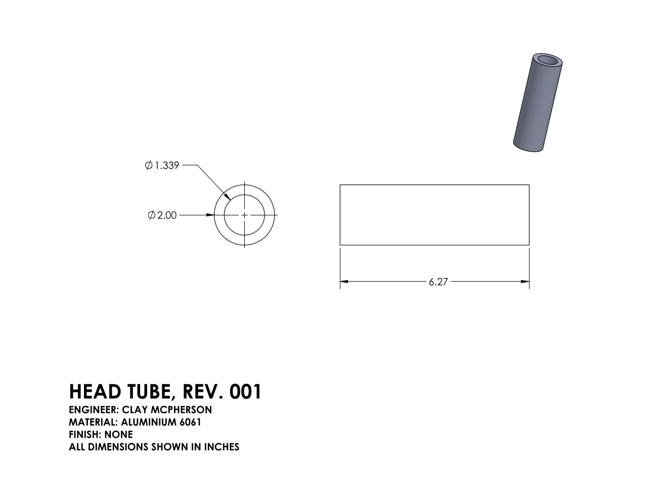
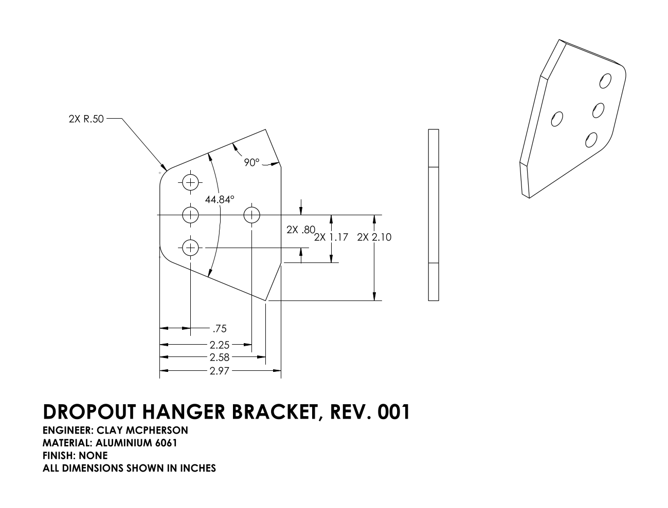
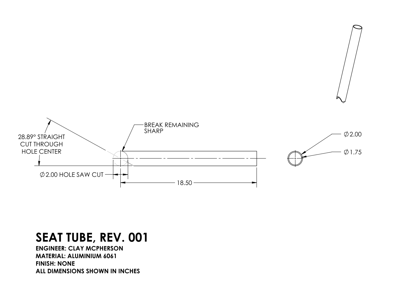
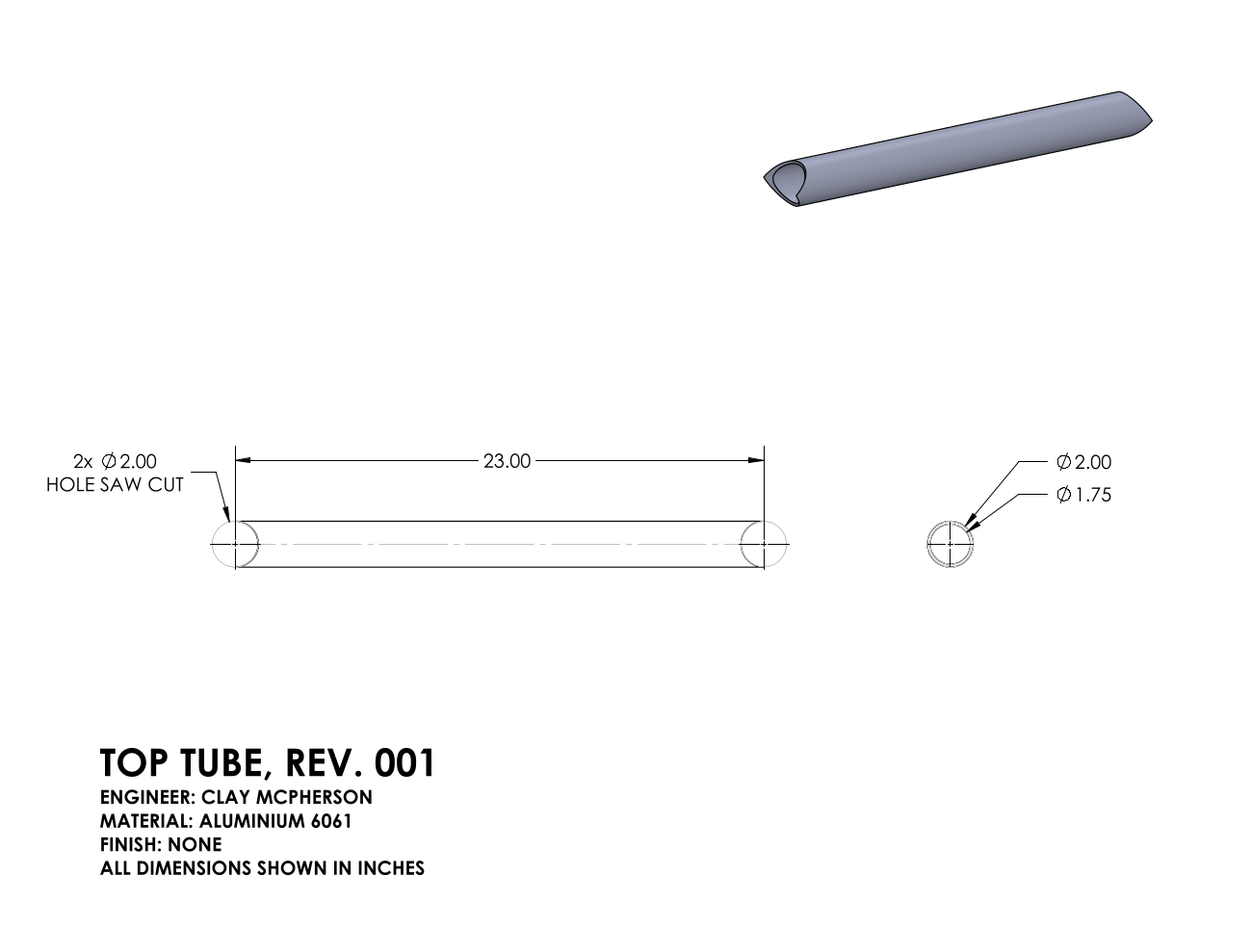
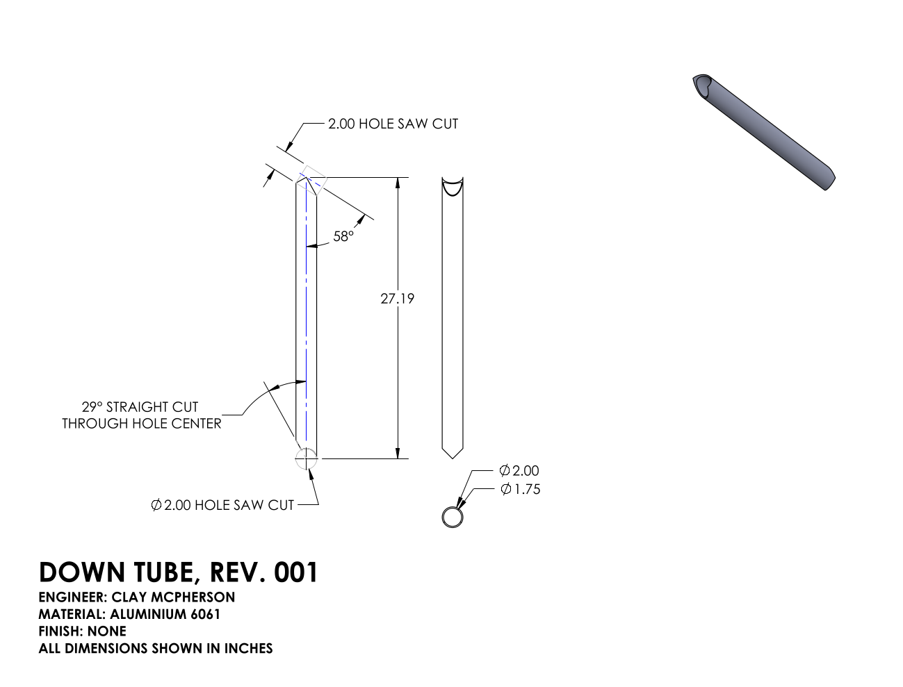
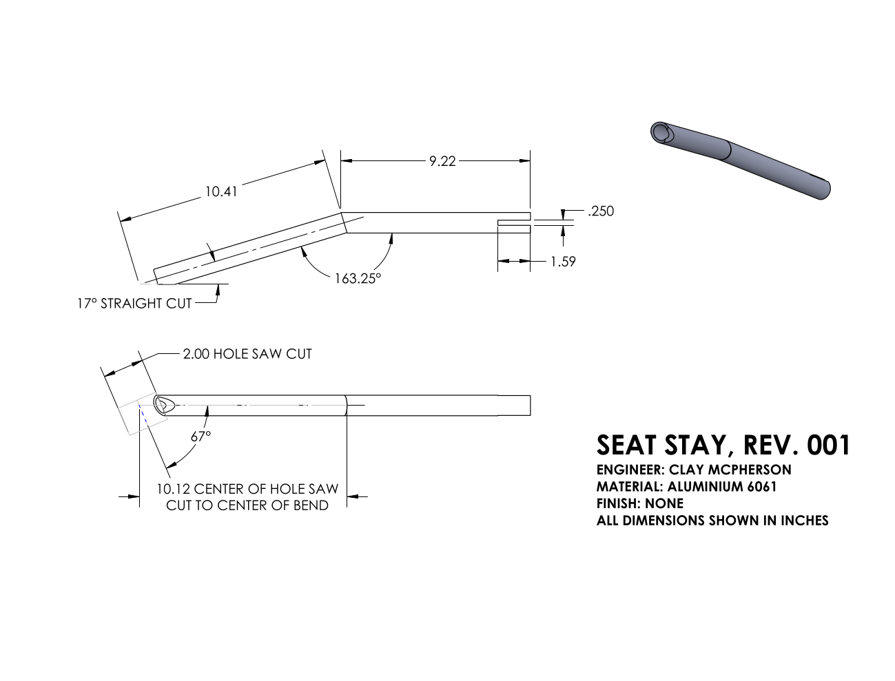
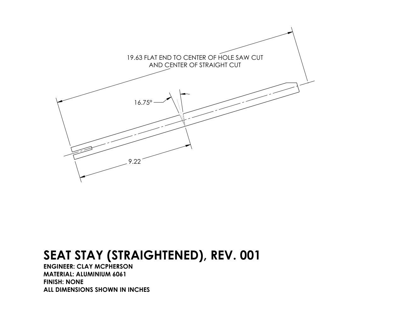
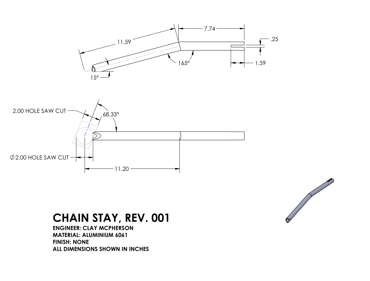
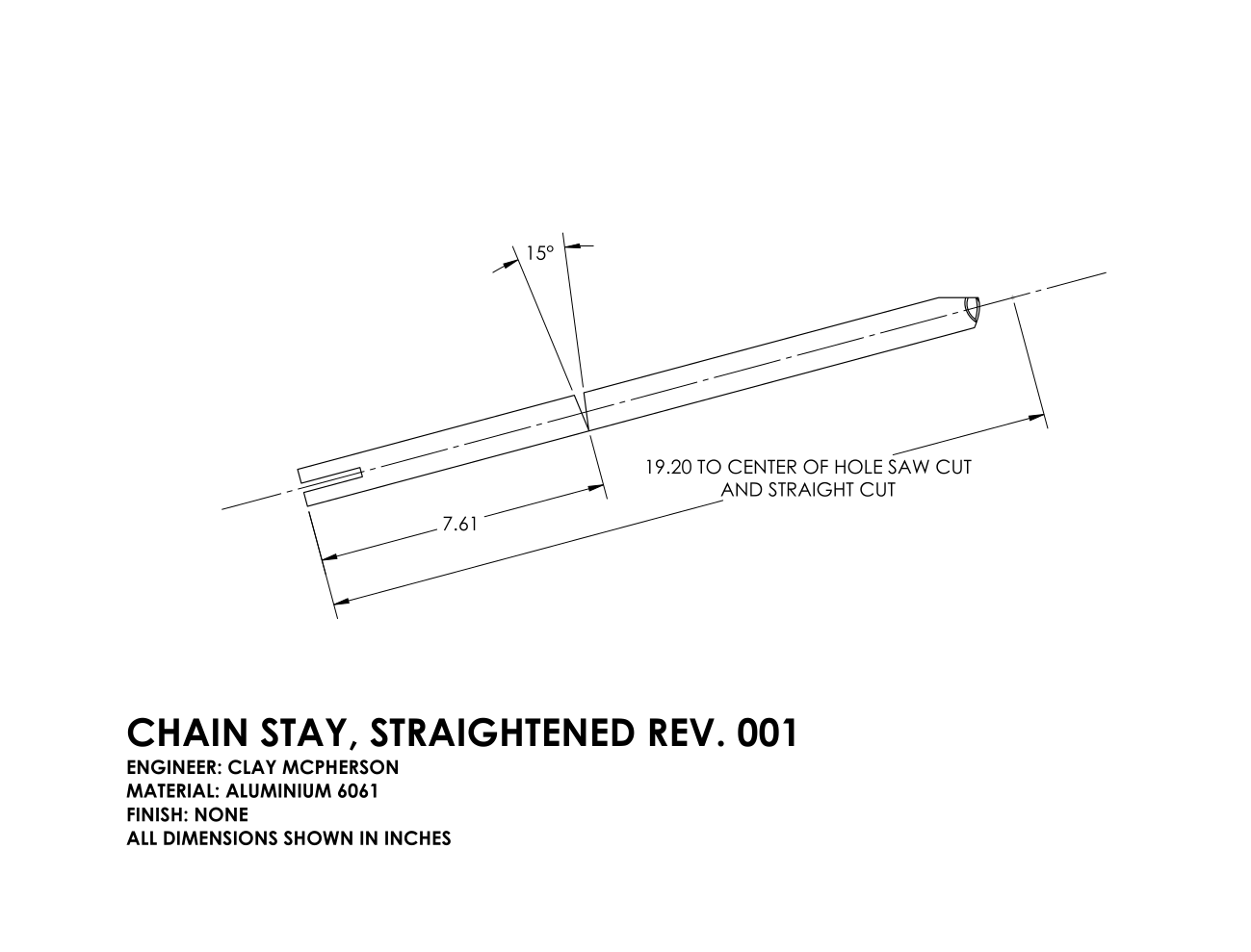

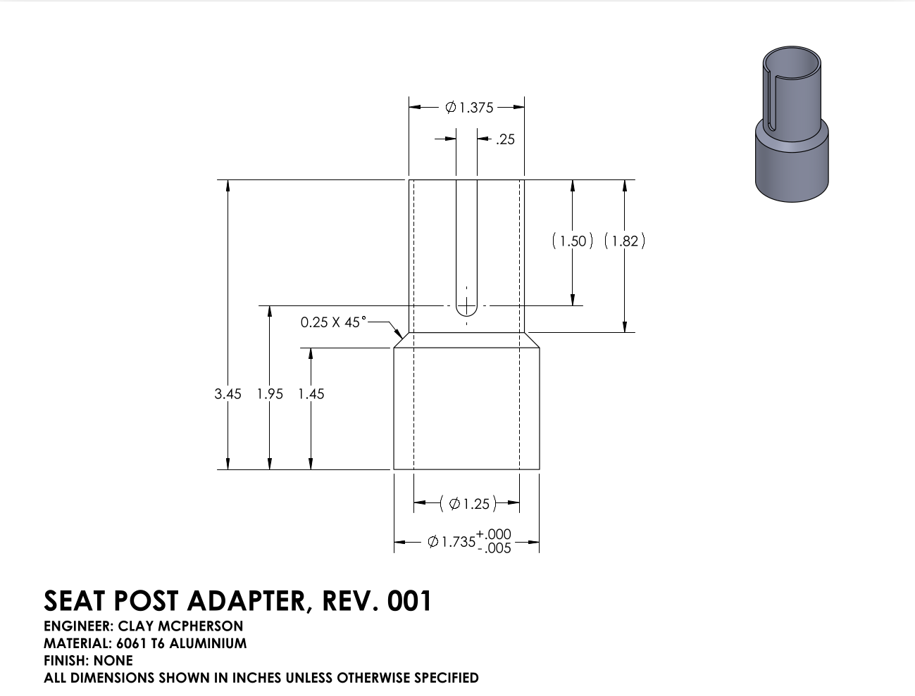
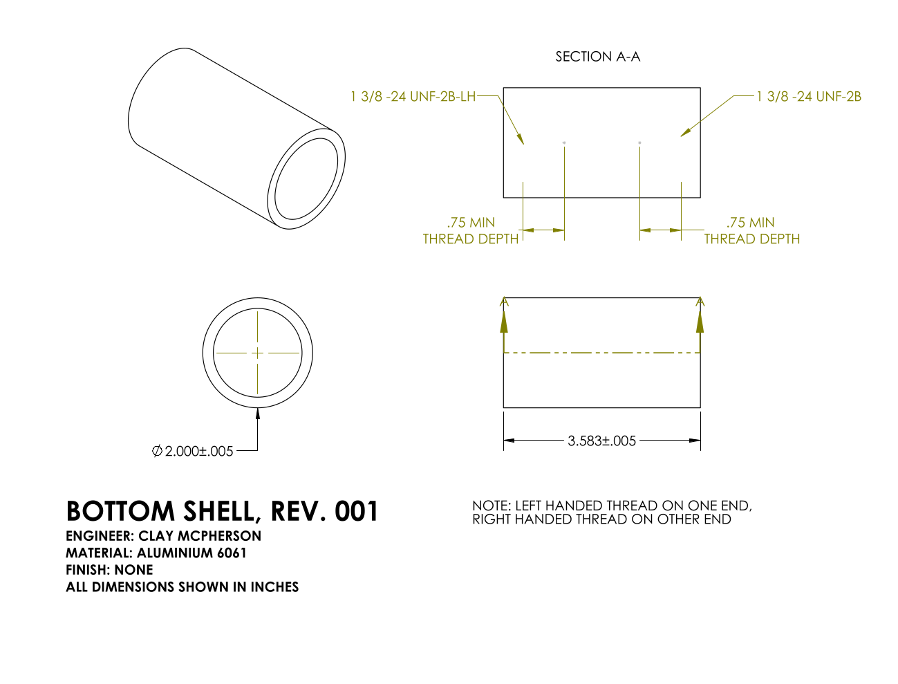
Here’s the overall geometry of my frame design. I chose these values mostly by measuring an existing bike I had and modifying a few dimensions to fit me better. I designed the individual parts to be as easy to manufacture as possible, requiring only 2 hole saws and containing no complex bends. All hole saw cuts were exactly centered through the tubes.
Here’s an action shot showing how I made all of the joints with a tubing notcher. I saved flat faces to use as datums for measurement purposes.
A few of my parts required some light machining, which I did on a manual mill and lathe. This was especially important for tight tolerance bearing fitments in the head tube and bottom bracket, as well as some features in the seat post adapter.
It was important to keep everything square and straight for the bike to handle properly. With the frame mostly tac welded together, I used straight edges and plumb bobs (bottom left of image) to measure parallelism of some important features. I could slightly tweak and bend the joints before fully welding them together.
The left image above is a closeup of the dropout feature. This is where the driven wheel mounts. I chose to make this a separate steel part which bolts on so that it could be modular. If the wheel alignment is a little off due to error in manufacturing the frame geometry, I can easily modify and replace the dropouts without cutting up the frame. I 3D printed several iterations of these first to get the wheel alignment exactly right in a test fit before having the final geometry cut from stainless steel. This area is also prone to fatigue stress from the cyclical torque pedaling the wheel, so I avoided aluminium here. The right image above shows my fixture jig I used while tac welding the frame together. It’s simply 3D printed brackets screwed to plywood with hose clamps fixing the tubes.
Here’s the completed bike. It’s about 30lb assembled, which is a little on the heavy side for a road bike. I built it primarily for casual street riding, and it rides fairly well. So far no issues in my first ~500 miles, but I do frequently inspect the joints for crack formation.


